Overview
Continuous Impact, Continuous Destruction. A beetleweight (≤1500 g) vertical spinner. Won its first event, Jogália; second event Maker Faire Porto. Results in the competition log.
C.I.C.D. replaced the Lucille MK2 drum, which was judged not efficient enough — see Vertical spinner over the MK2 drum. It keeps the reliable brushless 4WD drive and ELRS control that MK2 proved out; the weapon, chassis and drive layout are new.
It’s a hybrid chassis, not an all-printed robot: CNC-cut, hand-filed carbon-fibre plates sandwich a 3D-printed TPU body, carrying an 8 mm Hardox blade and forks.
At Porto the robot shut down after its own first weapon hit against Low Road, turning a won exchange into a loss. That points at the power/control path failing under shock: battery connector, ESC, wiring, or a receiver brownout. Top priority before the next event.
Also: no self-righting — being inverted cost a whole fight.
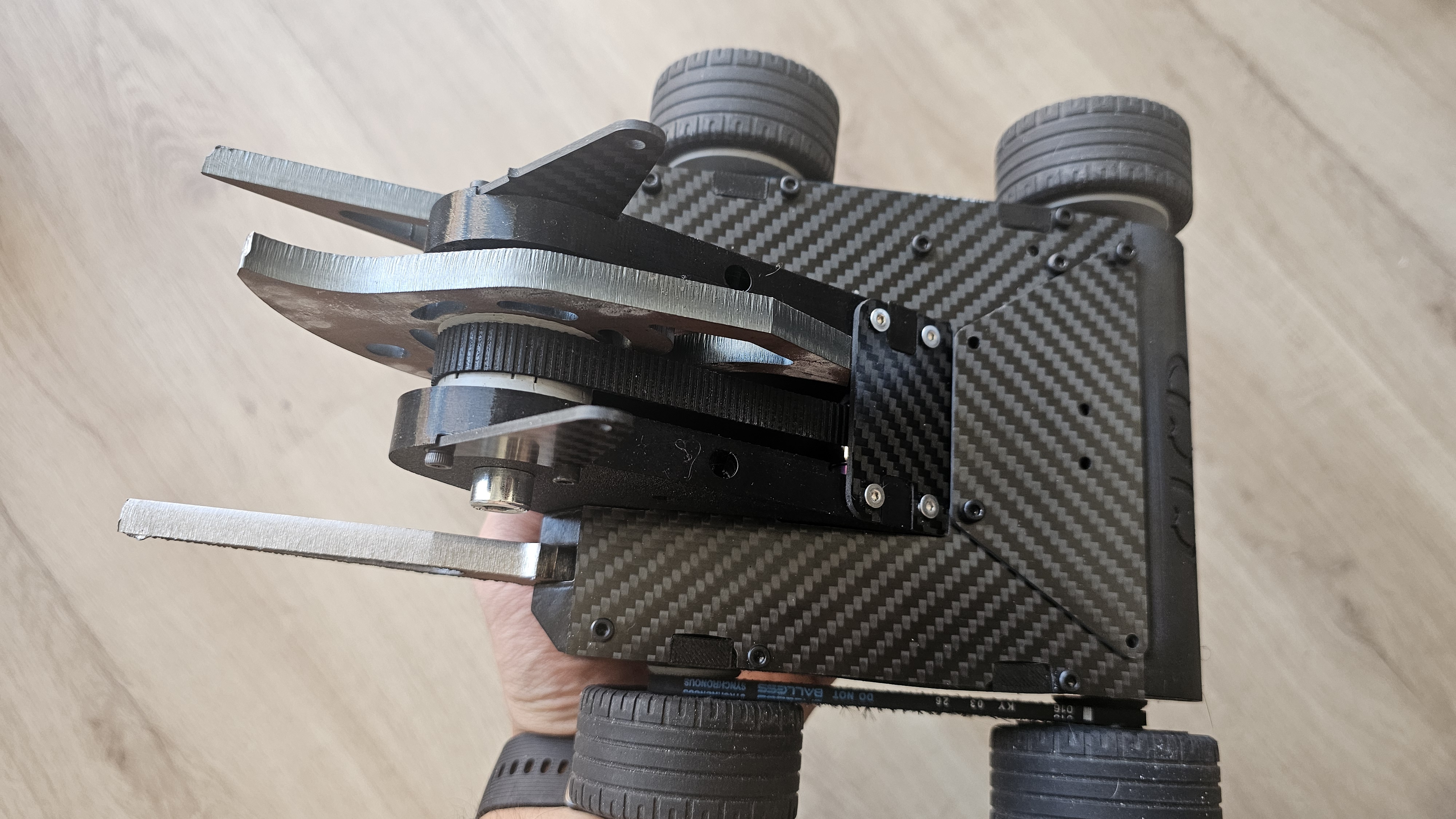 Assembled C.I.C.D. — carbon-fibre twill chassis plates; the machined Hardox Snaggletooth blade on its belt pulley (friction/slip belt drive); the two Hardox front forks with ground edges; 4× knobby wheels; socket-head bolt assembly. More in the photo album.
Weapon
Vertical spinner — single 8 mm Hardox Snaggletooth on a slip belt drive
A vertical spinner with a single Snaggletooth blade — one blade, not twin discs, because the 1500 g cap doesn’t allow two (Single blade, not twin discs).
Blade
- Design: the open-source Just’Cuz Robotics “Snaggletooth” (reference; CAD on their GrabCAD). Their stock is 6″ / 0.25″ AR500 — we used the design but had it machined locally in 8 mm Hardox.
- Material: 8 mm Hardox (abrasion-resistant steel) — for both the blade and the front forks.
- Mass: 277 g (Onshape mass properties, part
blade; volume 35,270 mm³ → density ≈ 7.85 g/cm³, confirming Hardox). - Spin-axis inertia: I ≈ 3.744×10⁻⁴ kg·m² (Lxx = 374.4 kg·mm², the largest principal moment, as expected for a flat bar’s spin axis; Lyy 104.6, Lzz 272.8). Axis still to verify against the motor-shaft mate connector.
- Hub/pulley radius: 30 mm. Tooth-tip radius not yet measured.
Drive — slip belt, 1:1
- Motor: D2830 1000 kv (carried over from MK2), on a 50A ESC.
- Ratio: single belt, 1:1 — weapon RPM = motor RPM (Weapon ratio — stay at 1-1).
- Friction / slip drive, no teeth. The belt runs directly on the motor. Slip is designed behaviour — a torque limiter that gives way on impact instead of passing the shock into the motor and ESC.
- Pulleys: printed in PLA.
A slip drive heats up every time it slips, and PLA softens around 60 °C — exactly the load it sees. Nylon (sponsored by: Evolt) is tougher, wears better and has far more heat margin, and the friction surface is the working surface. Status in Revisions.
| PLA (current) | Nylon | |
|---|---|---|
| Impact | Brittle | Tough |
| Wear | Poor | Much better |
| Heat | Softens ~60 °C | Far higher margin |
Bearings and shaft
Two 688 deep-groove ball bearings (8 × 16 × 5 mm) are embedded in the spinning weapon assembly (blade + pulley hub, Ø16 mm seats). They run on an M8 dead shaft that is fixed in the uprights and does not rotate. A 688 takes radial and axial load, so no thrust bearing is needed (Weapon bearings — 688 over needle rollers).
Weapon shaft hardware: M5×0.8×35 hex socket cap screw + M5 prevailing-torque thin nut (per CAD).
Uprights
The uprights hold the M8 dead shaft. They’re printed in TPU.
TPU uprights flex, and when they do the weapon pulley tilts out of line with the motor. The belt then runs at an angle and can walk off — the belt-derailment fault from Jogália, where it slipped into the blade’s spin path. 17% carbon-filled PET (sponsored by: Evolt) is stiff and dimensionally stable, so the pulley stays parallel and the belt stays on.
The trade: PET-CF is comparatively brittle — it resists deflection rather than absorbing impact. The TPU body still surrounds it, so energy absorption stays with the parts meant for it. Status in Revisions.
Performance (4S, 1:1)
- RPM: ~11,800 (1000 kv × 14.8 V × ~0.8 under load) → ω ≈ 1236 rad/s
- Stored energy: ~286 J (E = ½·I·ω²) — at the bottom of the competitive beetleweight window (~300–700 J)
- Tip speed: ~43–56 m/s (firms up once the tooth-tip radius is measured)
Drive & Wheels
Brushless 4WD, one motor per side belting the front wheel; 3-part printed hubs on Lego tyres
Drive
- 4WD, 2× 2322 brushless motors with 25:1 planetary gearboxes, one per side (inherited from Lucille MK2).
- Each motor mounts on the rear wheel and drives the front wheel through a single belt, 1:1 (no reduction) — changed from MK2’s mid-mounted, dual-belt layout.
- Drive ESCs: 2× 40A, one per side.
- Wheel pulley: 22 mm, GT2.
Wheels
The tyre is a 56×28 RZ Lego tyre — bought, not printed. It sits on a 3-part printed hub: an outer ring, a central drum the tyre seats on, and a sprocket side carrying the GT2 pulley and the bore, running on a 625-ZZ bearing (CAD: tire_56_x_28 + 56x28rz_sprocket + 625-zz).
The current hubs are the Jogália build. At Jogália the rims were too brittle and the hub screws worked loose.
Those two failures want opposite properties — brittle rims need compliance, loose screws need stiffness and thread retention. One material can’t do both, but three parts can:
| Part | Material | Why |
|---|---|---|
| Outer ring | TPU 95A | The compliant element — flexes under impact instead of cracking |
| Central drum (tyre seats here) | Nylon (sponsored by: Evolt) | Structural body; tough without being brittle |
| Sprocket side (GT2 pulley + bore) | Nylon (sponsored by: Evolt) | Carries belt torque through the GT2 teeth and holds the hub screws |
The structural load path stays entirely in nylon (drum → sprocket plate → belt), with TPU as a single compliant ring rather than a load-bearing member. Status in Revisions.
Chassis & Electronics
Carbon-fibre plates around a TPU body; 4S power, XT30 distribution, ELRS control
Chassis
A hybrid chassis, not an all-printed robot:
- Top and bottom plates: 2 mm carbon fibre (twill), CNC-cut from the
cf_cutsprofile in CAD, then hand-filed to finish the edges. “CICD” is engraved in the lower plate. The plates double as the armour. - Body structure: 3D-printed TPU between the plates — compliant, so it absorbs impacts rather than cracking.
- Weapon uprights: TPU — see Weapon.
- Assembly: socket-head bolts throughout.
Power
- Battery: 4S 650 mAh Tattu (14.8 V) — the primary pack in the CAD assembly.
- Distribution: XT30 distribution board (
XT30_DIST_BOARD_LC). - ESCs: 50A weapon, 2× 40A drive.
Control
Inherited from Lucille MK2 / Lucille:
- RadioMaster ER6 ExpressLRS 2.4 GHz PWM receiver
- EdgeTX radio, model slot
CICD
Revisions
Build versions and the status of every pending change
Each change moves through designed → printed → fitted → tested.
v1 — Jogália build (fighting now)
The build that won Jogália 2026 (11–12 Jul 2026) and fought Maker Faire Porto 2026 (18–20 Sep 2026) unchanged.
- TPU weapon uprights, PLA weapon pulleys
- Original 3-part wheel hubs
- Single-blade Hardox Snaggletooth, 1:1 slip belt, 688 bearings on the M8 dead shaft
Known faults carried by v1:
- Brittle wheel rims; hub screws working loose (Jogália)
- Weapon belt can walk off into the blade’s spin path (Jogália)
- Shuts down under its own weapon impact (Porto) — cause unknown
- No self-righting
v2 — post-Jogália upgrades (in progress)
Made for Maker Faire Porto but not assembled in time, so Porto ran v1.
| Change | Fixes | Rationale | Status |
|---|---|---|---|
| Weapon uprights TPU → PET-CF (sponsored by: Evolt) | Belt walking off | Weapon | Printed — not fitted |
| Weapon pulleys PLA → nylon (sponsored by: Evolt) | Slip-drive heat and wear | Weapon | Printed 2026-09-10 — not fitted |
| Wheel hubs: TPU outer ring + nylon drum and sprocket | Brittle rims, loose hub screws | Drive & Wheels | Printed 2026-09-10 — not fitted |
Still open for v2: the cause of the weapon-impact shutdown, and self-righting.
CAD
Onshape document, configurations and renders
Document: C.I.C.D. on Onshape — the source of truth for dimensions and masses.
As with Lucille MK2, Onshape’s Front plane looks at the rear of the robot — CAD +Y points away from the weapon, but in combat the weapon/fork side is the front. Mentally flip when reading views or mass-property axes.
Configurations (front-end variants): Clean (bare chassis) · Forks (single-blade spinner — the competition build) · Wedge.
Tabs: Assembly · Body · WeaponMountAssembly · WeaponMount · Weapon (parts blade, bar, +2) · armor · old · cf_cuts (+ Sketch 1.dxf) · drive motors.
Assembly instances (Forks config, 17): Body · drive motors · 4s650-tattu · 50A (weapon ESC) · 2× 40A (drive ESCs) · 3s850-MiniStar · 2× 56x28rz assembly (wheel hubs) · WeaponMountAssembly + Mirror 1 · XT30_DIST_BOARD_LC · Jackei-fork (weapon) · Assembly 1 · armor · M5×0.8×35 cap screw + M5 thin nut (weapon shaft). 10 fastened mates.
Renders
Forks configuration, captured 2026-07-14.
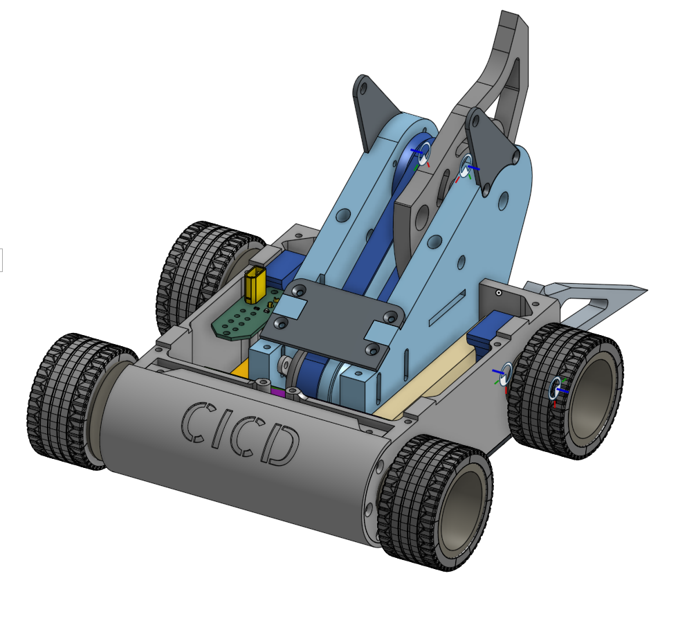 Isometric — 4WD chassis with “CICD” embossed, blue weapon-mount towers, drive belts, electronics tray, fork weapon at the front.
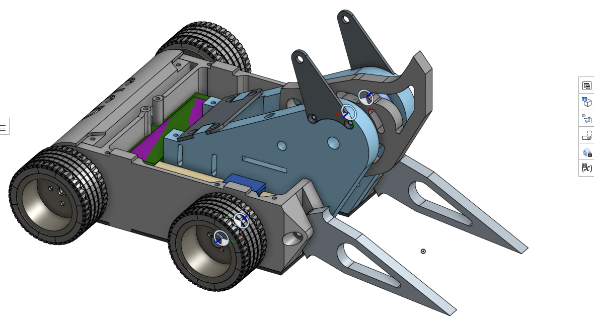 Front three-quarter — the two Hardox forks extending forward, the blade behind them; drivetrain, PCB and weapon mount exposed.
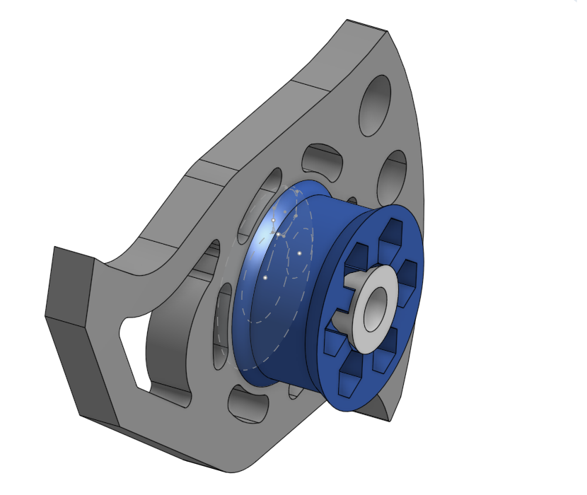 Weapon part studio — Hardox blade/fork plate (grey) + belt pulley and toothed hub (blue).
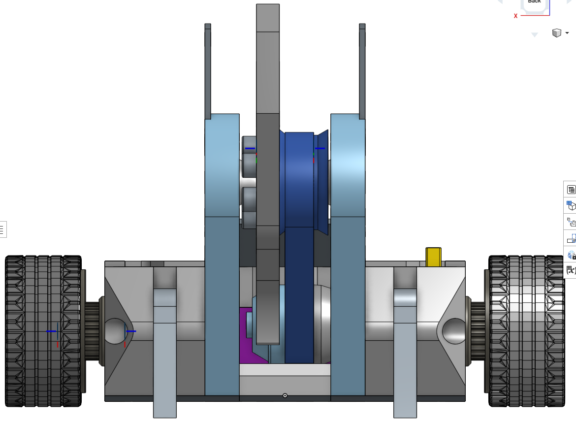 Onshape Back = robot front — the Snaggletooth blade and pulley centred, flanked by the weapon towers and drive wheels.
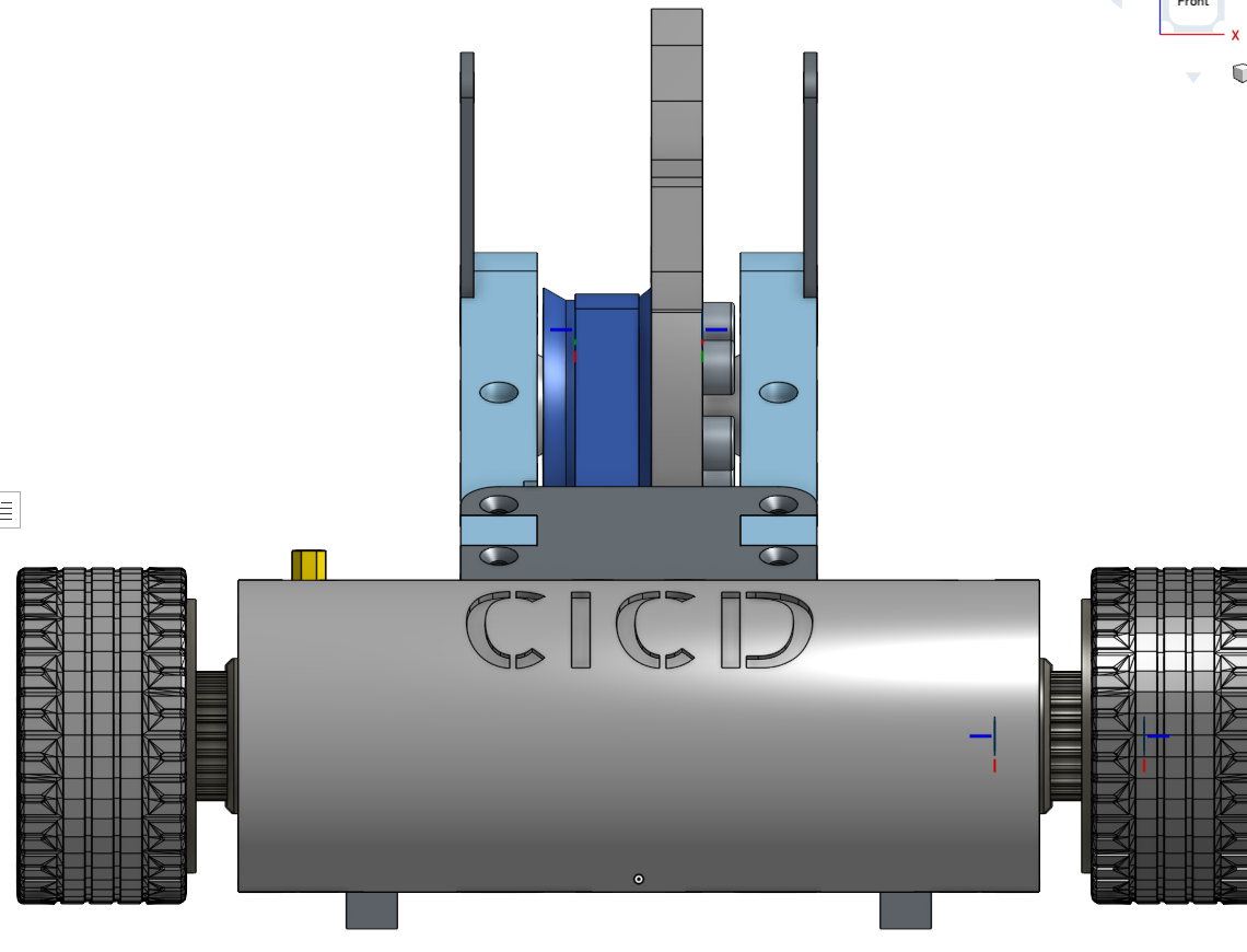 Onshape Front = robot rear — “CICD” barrel, wheels, weapon towers behind.
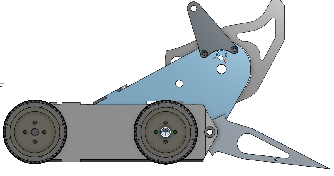 Onshape Right = robot’s left side — fork prongs, raised weapon arm, wheelbase.
Design decisions
What we chose, what we rejected, and why.
Single blade, not twin discs
accepted An early concept twinned two co-axial discs; there's no weight budget for two blades under 1500 g
Single blade, not twin discs
acceptedDecision: a single Snaggletooth blade. Rejected: two co-axial discs.
An early concept twinned two discs on the weapon axis. There’s no weight budget for two blades in the 1500 g cap — the single 8 mm Hardox blade alone is 277 g.
The Onshape document keeps three front-end configurations — Clean, Forks (the competition build) and Wedge.
Vertical spinner over the MK2 drum
accepted The Lucille MK2 drum was judged not efficient enough; C.I.C.D. is a new robot built around a vertical spinner
Vertical spinner over the MK2 drum
acceptedDecision: build a new robot around a vertical spinner. Rejected: continuing the Lucille MK2 horizontal drum.
The MK2 drum was judged not efficient enough. A vertical spinner gives vertical bite and the potential to self-right — and it’s the “meta” weapon in the class.
Kept from MK2: the brushless 4WD drive motors and gearboxes, and the ELRS control stack, which had already proved reliable. New: the weapon, the chassis and the drive layout.
Weapon bearings — 688 over needle rollers
accepted Kept two 688 ball bearings in the weapon hub; needle rollers would have needed thrust bearings and ended up heavier
Weapon bearings — 688 over needle rollers
acceptedDecision (Sep 2026): keep the two 688 deep-groove ball bearings (8 × 16 × 5 mm) embedded in the spinning weapon assembly, running on the M8 dead shaft. Rejected: 2× HK0808 drawn-cup needle rollers.
Why the needles lost
Needle rollers carry radial load only. With no axial capacity, the rotating hub would need separate thrust bearings to stop the blade walking along the shaft — and a vertical spinner takes real side loads on impact.
That turns a clean 2-bearing setup into needles + thrust washers/bearings + the stack height to house them, which came out heavier than the 688s. A 688 takes radial and axial load in one part, so it needs no thrust bearing.
The needles’ higher radial rating was real, but radial capacity was never the binding constraint — 1500 g is.
The rejected proposal
- 2× HK0808, straddle-mounted (one at each end of the hub — splits impact load, resists cocking)
- Bore 8 mm (fits the M8 shaft) · OD 12 mm · width 8 mm → hub bore Ø12 mm, ≥16 mm deep
- Dynamic Cr ≈ 2.55–2.75 kN, static Cor ≈ 2.4–2.6 kN per bearing
- Speed ~14,000 rpm (grease) / ~19,000 rpm (oil); DIN 618-1 / ISO 3245
- At ~11,800 rpm that’s ~84% of the grease limit — little headroom, and a 2:1 step-up (~23,600 rpm) would destroy them
- Drawn cups need a hardened shaft as the inner race — the M8 would have to be a hardened dowel, not a cap screw
Revisit if
Bearing failures show up in the 688s under impact, or the weight budget frees up.
Weapon ratio — stay at 1-1
accepted 1:1 already stores ~286 J; a 2:1 step-up (~1140 J) would outrun the chassis, belt and bearings
Weapon ratio — stay at 1-1
acceptedDecision: keep the weapon belt at 1:1. Rejected: a 2:1 step-up.
With the 277 g Hardox blade (I ≈ 3.744×10⁻⁴ kg·m²) at ~11,800 rpm, 1:1 already stores ~286 J — at the bottom of the competitive beetleweight window (~300–700 J).
A 2:1 step-up would push ω to ~2470 rad/s and ~1140 J — likely more than the chassis, belt and mounts can survive, and well past the speed limit of any bearing that fits the hub.
Revisit if
Impacts prove weak in fights, or the spin-axis check changes the inertia figure.
Competition log
-
Maker Faire Porto
3–3 overall (RR 1–1, bracket 2–2) — eliminated by Samurai, the event winnerevent2026-09-18 location_onAlfândega do PortoSecond event for C.I.C.D. (18–20 September 2026), run by Liga REC.
Ran the Jogália build — none of the new parts were testedNo time to test the new hardware, so C.I.C.D. fought in exactly the Jogália configuration. The PET-CF (sponsored by: Evolt) uprights, nylon (sponsored by: Evolt) pulleys and the redesigned wheels were all printed but never went in.
Which means the Jogália faults were still live: brittle rims, loosening hub screws, and the belt that can derail into the blade arc.
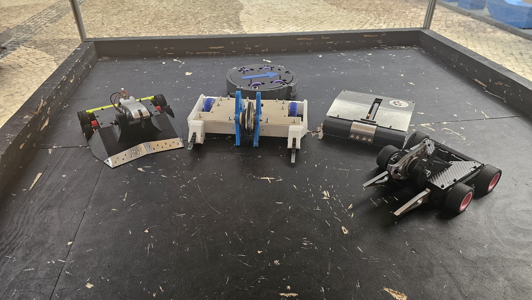
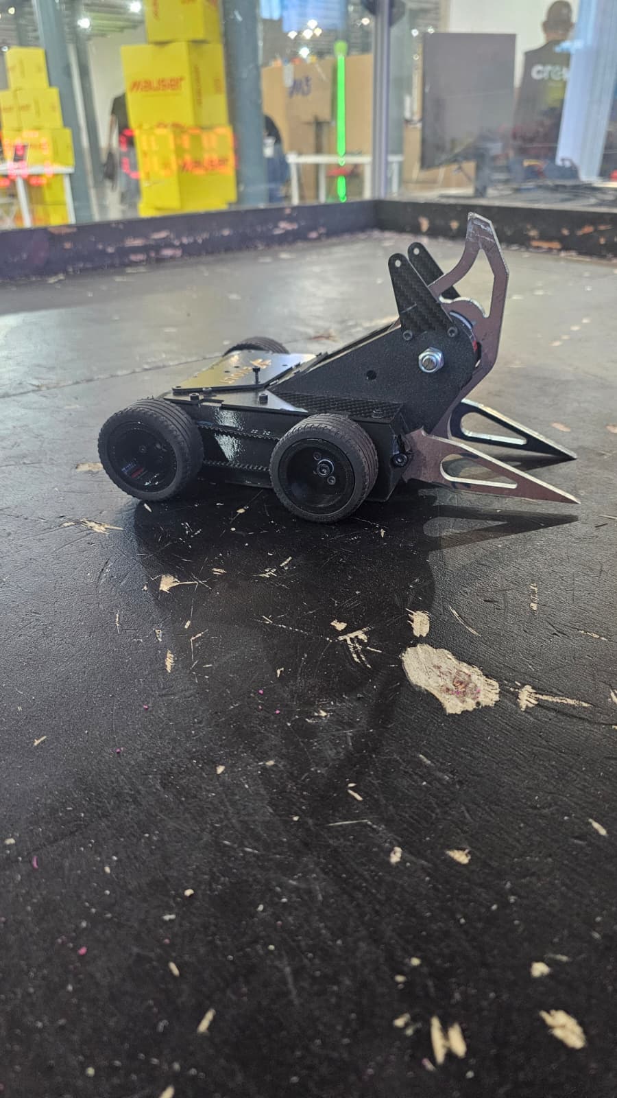 C.I.C.D. in the arena at Maker Faire Porto.
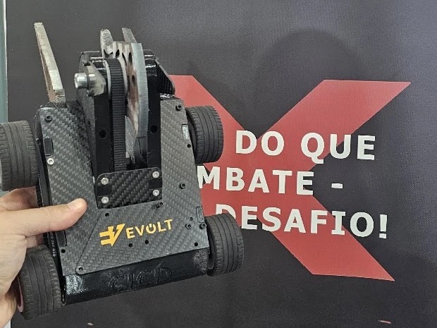
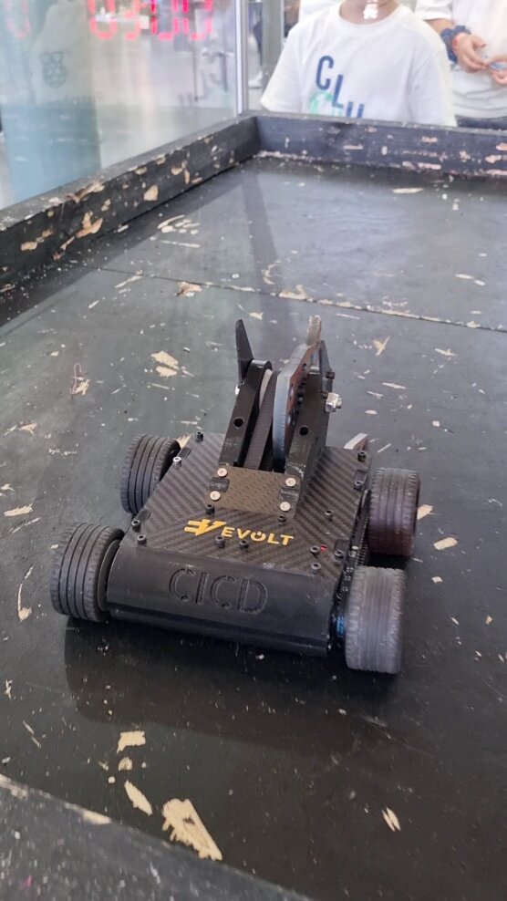 C.I.C.D. on the arena floor — Evolt‘s sticker on the carbon-fibre top plate, the black TPU
body with the raised CICD lettering, the Hardox forks and blade folded over the front. The
sponsor placement agreed for this event, in position.
C.I.C.D. on the arena floor — Evolt‘s sticker on the carbon-fibre top plate, the black TPU
body with the raised CICD lettering, the Hardox forks and blade folded over the front. The
sponsor placement agreed for this event, in position.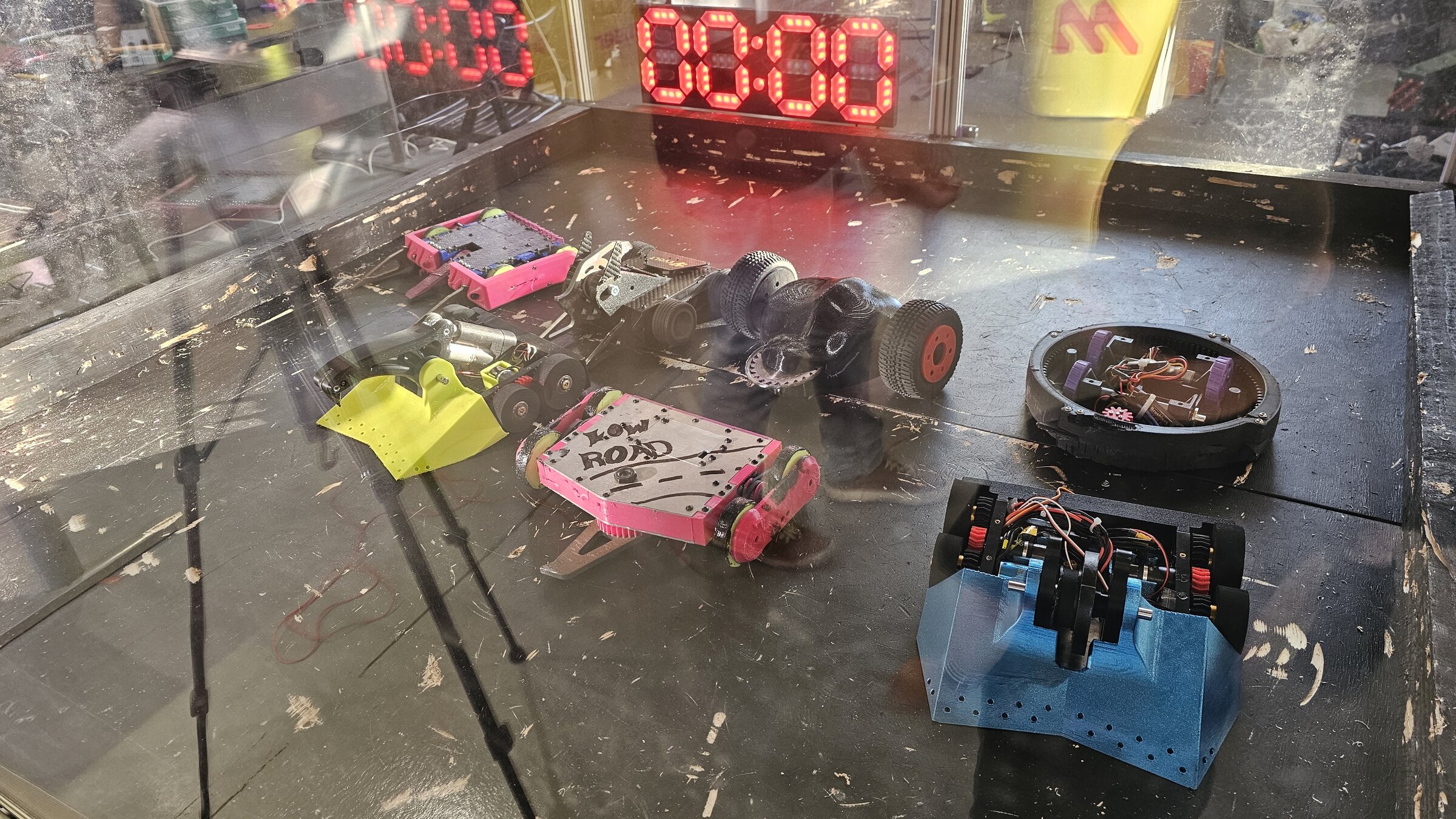 The Liga REC field in the arena on the Friday. Clockwise from the back left:
wobbegong (pink rails, carbon deck, yellow-green wheels), C.I.C.D. (carbon plate with
the Evolt sticker), Chaos Thing (dark body, red hub inserts, saw blade),
Orbit.exe (black ring shell spinner, purple internals), SpinnerLord (blue perforated
wedge, vertical spinner), Low Road (pink, hand-lettered, undercutter) and PressLord
(yellow scoop with the overhead arm). Samurai is absent — that team arrived on the
Saturday.
The Liga REC field in the arena on the Friday. Clockwise from the back left:
wobbegong (pink rails, carbon deck, yellow-green wheels), C.I.C.D. (carbon plate with
the Evolt sticker), Chaos Thing (dark body, red hub inserts, saw blade),
Orbit.exe (black ring shell spinner, purple internals), SpinnerLord (blue perforated
wedge, vertical spinner), Low Road (pink, hand-lettered, undercutter) and PressLord
(yellow scoop with the overhead arm). Samurai is absent — that team arrived on the
Saturday.Format
Round robin, then a double-elimination bracket.
The export looks incompleteThe tournament export records 9 round-robin matches, but that doesn’t cover everything fought — my own recollection includes a KO over Orbit.exe in the group phase that isn’t in the data. Treat the export as partial: names and bracket results are authoritative, round-robin coverage probably isn’t.
Names below follow the export: SpinnerLord, PressLord, Orbit.exe, wobbegong.
Round robin — as exported
# A B Winner How Pts 1 PressLord Orbit.exe Orbit.exe jury 2 2 Chaos Thing wobbegong wobbegong jury 2 3 CICD SpinnerLord CICD ko 3 4 Samurai Orbit.exe Samurai ko 3 5 Dummy wobbegong wobbegong jury 2 6 Low Road SpinnerLord Low Road ko 3 7 Samurai PressLord Samurai jury 2 8 Dummy Chaos Thing Chaos Thing jury 2 9 Low Road CICD Low Road ko 3 Dummy is a test entry, not a real robot — used to balance the round robin.
Scoring: KO = 3 points, jury decision = 2.
C.I.C.D. in the round robin: 1–1. KO’d SpinnerLord; lost to Low Road by KO — the fight where my own robot shut down after landing the first hit (see below).
Bracket — double elimination
Round A B Winner How QF1 Low Road bye Low Road bye QF2 CICD Chaos Thing CICD jury QF3 Samurai bye Samurai bye QF4 wobbegong Orbit.exe wobbegong jury SF1 Low Road CICD Low Road ko SF2 Samurai wobbegong wobbegong ko Winners Final Low Road wobbegong wobbegong jury LR1·A bye Chaos Thing Chaos Thing bye LR1·B bye Orbit.exe Orbit.exe bye LR2·A Chaos Thing Samurai Samurai ko LR2·B Orbit.exe CICD CICD ko LR3 Samurai CICD Samurai ko Losers Final Samurai Low Road Samurai ko Grand Final wobbegong Samurai Samurai jury C.I.C.D. in the bracket: 2–2. Beat Chaos Thing (jury) and Orbit.exe (KO); lost to Low Road (KO) and Samurai (KO).
Both SF1 and LR3 were KOs against usLosing by KO twice in the bracket is consistent with the shutdown fault — see below. Worth checking whether either was a genuine knockout or another self-inflicted stop.
Overall records
Robot Round robin Pts Bracket KO for KO against Total Samurai 2–0 5 4–1 4 1 6–1 🏆 wobbegong 2–0 4 3–1 1 0 5–1 🥈 Low Road 2–0 6 1–2 3 1 3–2 🥉 CICD 1–1 3 2–2 2 3 3–3 Orbit.exe 1–1 2 0–2 0 2 1–3 Chaos Thing 1–1 2 0–2 0 1 1–3 PressLord 0–2 0 — 0 0 0–2 SpinnerLord 0–2 0 — 0 2 0–2 Low Road topped the round robin on points6 points from two KO wins — the highest of anyone, including the eventual winner. Then went 1–2 in the bracket. It was the strongest group-stage robot and the one that beat us twice.
Event outcome
🏆 Winner Samurai — beat wobbegong in the Grand Final and the reset match Runner-up wobbegong — undefeated through the winners bracket, lost both Grand Final matches Also Low Road — out to Samurai in the Losers Final Samurai eliminated both our robots and then won the whole thing.
Chaos Thing also competed
Chaos Thing — Ricardo’s robot, its first event — went 1–3 in the tournament: round robin 1–1 (lost to wobbegong, beat the Dummy balancing entry), then 0–2 in the bracket (C.I.C.D., then Samurai). Its first ever win came on the Friday, before the group phase — a real match, but outside the tournament, against wobbegong.
Worth noting C.I.C.D. only beat it on a judge decision, not a KO.
Two findings from that robot that matter beyond it:
- The full-TPU body was very reliable. Four fights, no structural trouble. Compliance beats rigidity for a body shell.
- The wood blade hit hard — real damage to opponents and the arena — but the blades aren’t durable enough. More durable blades needed next time.
LowRoad — twice, and the pattern matters
First fight. Landed the opening hit and tossed LowRoad into the roof of the box. Killed its right drive and did nasty damage to its aluminium plates. Then my robot shut down — after my own initial hit.
This is the fight to understandI did the damage, won the exchange, and still lost — because C.I.C.D. stopped. A shutdown triggered by my own weapon impact points at something in the power or control path that isn’t surviving shock: battery connector, ESC, wiring, or a brownout on the receiver.
That is not a driving problem or a weapon problem. It’s the most important thing to come out of this event.
Second fight. Judge decision. Got inverted early and had to drive defensively from there. Tried to jam the weapon and forks into LowRoad’s weapon — no real success. Again did major damage to LowRoad but couldn’t finish it.
The pattern across both: plenty of damage output, no ability to close. LowRoad absorbed heavy hits twice and kept going.
Samurai — the exit
Lost by tap-out. Close match — and Samurai went on to win the whole event, so it was the eventual champion that put both our robots out.
What this event actually showed
- Something shuts C.I.C.D. down under its own weapon impact. Highest priority by a distance — it converted a won fight into a loss.
- No self-righting. Being inverted against LowRoad forced a whole fight of defensive driving. This was already flagged as TBD on CICD; it now has a cost attached.
- Damage output is fine; finishing isn’t. Two fights of major damage to LowRoad without a kill.
- The untested upgrades stay untested. Everything printed for this event is still on the bench.
- TPU bodies work. Chaos Thing‘s all-TPU shell came through four fights intact — worth weighing for future builds.
Related
- CICD · Jogália 2026 · Chaos Thing — Ricardo’s, 1–3 · REC
- Opponents: Liga REC Robots — Samurai · wobbegong · Low Road · Orbit.exe · SpinnerLord · PressLord
-
Jogália
🏆 Winnerevent2026-07-11 location_onInstituto Superior Técnico, Tagus Park (Oeiras)First event C.I.C.D. entered — won the tournament (11–12 July 2026).
What went wrong
- Wheels were the weak point. The rims were too brittle and took damage over the fights.
- Hub screws didn’t tighten properly — wheels worked loose; needs a better hub/fastener scheme.
Risks to fix before the next event
- Weapon belt keeps slipping into the weapon’s spin path — a belt jump/derail near the spinning blade is a reliability and safety hazard. Needs a guard or a re-route/tensioner so the belt can’t reach the blade arc.